


MTW European Type Trapezium Mill
Input size:30-50mm
Capacity: 3-50t/h

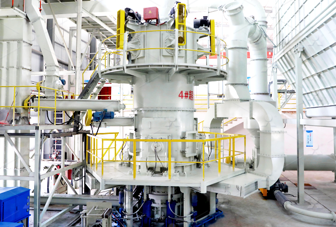
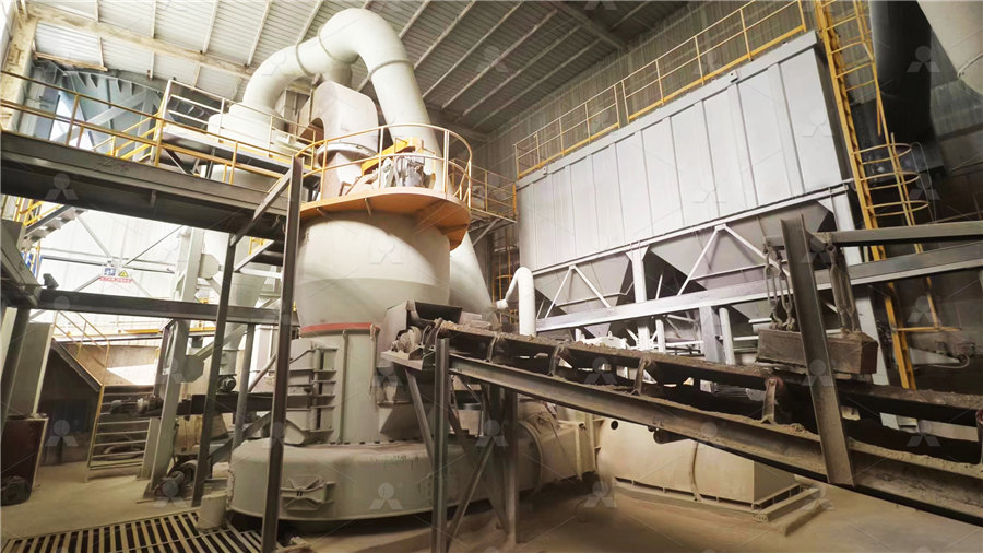
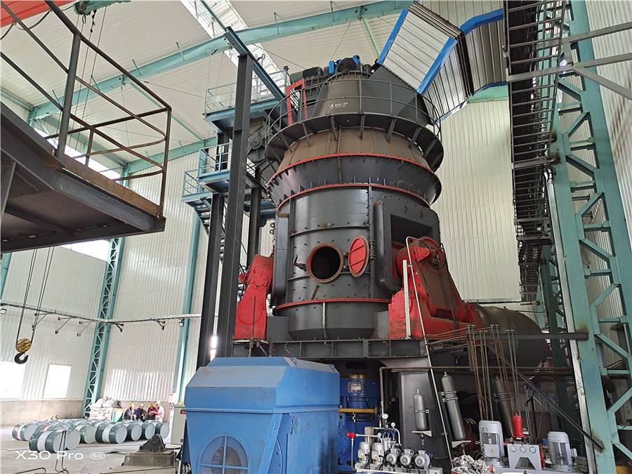
LM Vertical Roller Mill
Input size:38-65mm
Capacity: 13-70t/h
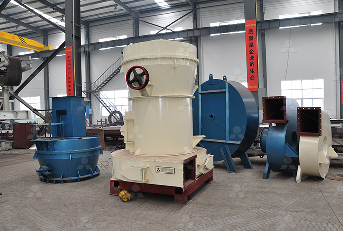
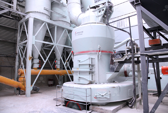
Raymond Mill
Input size:20-30mm
Capacity: 0.8-9.5t/h
Sand powder vertical mill
Input size:30-55mm
Capacity: 30-900t/h
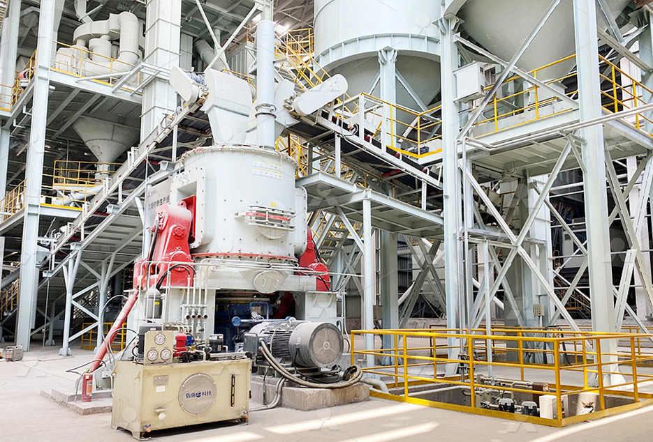
LUM series superfine vertical roller grinding mill
Input size:10-20mm
Capacity: 5-18t/h
MW Micro Powder Mill
Input size:≤20mm
Capacity: 0.5-12t/h

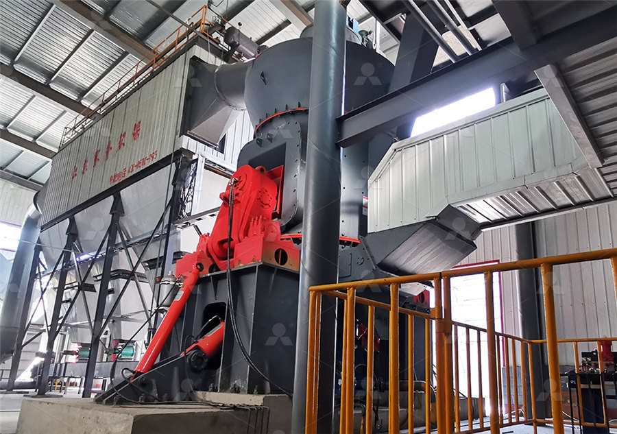
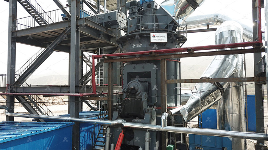
LM Vertical Slag Mill
Input size:38-65mm
Capacity: 7-100t/h

LM Vertical Coal Mill
Input size:≤50mm
Capacity: 5-100t/h
TGM Trapezium Mill
Input size:25-40mm
Capacity: 3-36t/h
MB5X Pendulum Roller Grinding Mill
Input size:25-55mm
Capacity: 4-100t/h
Straight-Through Centrifugal Mill
Input size:30-40mm
Capacity: 15-45t/h
Electrical circuit diagram of port Raymond mill
.jpg)
Schematic diagram of a raymond mill system ResearchGate
To achieve this goal, it is proposed a new automatic control system (ACS) for ore volumetric filling of gratedischarge ball mill in a closed grinding cycle using model predictive control and To achieve this goal, it is proposed a new automatic control system (ACS) for ore 登录2020年4月21日 All electrical control parts of Raymond mill are assembled in the electrical control cabinet, and centralized control is implemented (see circuit principle, see diagram, electricElectrical Control of Raymond Mill LinkedIn2016年3月28日 Schematic diagram of a raymond mill system Block diagram of the disturbance observerenhanced MPC method Control structure of constant current of raymond posite control for raymond mill based on model predictive
Composite control for raymond mill based on model predictive
2016年1月5日 In order to address this issue, a widely used method in raymond mill control system is to use a programmable logic controller (PLC), electromagnetic vibration feeder, and Raymond Mill The Raymond grinding mill, Raymond mill for short, is a roller mill in which the central spindle drives the multiple grinding rollers installed on the plumblossom rack to swing Roller Mill Springer2021年11月15日 An electrical schematic is a diagram that shows how all of the wires and components in an electronic circuit are connected They’re like a map for building or troubleshooting circuits, and can tell you almost everything you How to Read Electrical Schematics Circuit BasicsA basic electrical circuit (Diagram) consists of three main components: the source, the load, and the conductors The battery has two terminals These terminals are connection points for the two conductors One terminal is Basic Electrical Circuit: Theory, Components,
.jpg)
ELECTRICAL CIRCUIT ANALYSIS Lecture Notes
differential equations which are the governing equations representing the electrical behavior of the circuit A circuit having a single energy storage element ie either a capacitor or an Inductor is called a Single order circuit and it’s governing equation is called a These two different types of circuit diagrams are called pictorial (using basic images) or schematic style (using industry standard symbols) A schematic style circuit diagram is used to give a visual representation of an electrical circuit to an electrician The pictorial style circuit diagram would be used for a broader, less technical Circuit Diagram Learn Everything About Circuit DiagramsContact normally closed (E 2)if the associated variable E 2 is ‘1’, the contact remains open, and if it is ‘0’, it is closed Output, coil, or relay (S 1) – the associated variable S 1 will take the value of the variable The key feature of ladder logic is that it does not necessarily reflect the physical layout of the components in the realworld electrical panelElectrical Diagrams and Schematicsabout the Electrical Circuits and Simulation By this perspective we have introduced a Laboratory manual cum Observation for Electrical Circuits and Simulation The manual uses the plan, cogent and simple language to explain the fundamental aspects of Electrical Circuits and Simulation in practical The manual prepared very carefully with our levelLaboratory Manual Electrical Circuits and Simulation

What is Raymond Mill? How Does It Work? alwepo
2024年9月4日 Raymond Mill Ultrafine Mill: This machine is used for grinding extremely fine materials, even down to 3000 mesh It’s often used for materials that are challenging to process with regular milling machines, such as graphite, coal, and othersRaymond Mill The Raymond grinding mill, Raymond mill for short, is a roller mill in which the central spindle drives the multiple grinding rollers installed on the plumblossom rack to swing outwardly under the action of centrifugal force and press the grinding ring on the inner wall of the casing to grind the materialRoller Mill SpringerYes, you can hire a professional electrician or technician to create a wiring diagram for your Bridgeport milling machine They will have the knowledge and experience to accurately diagram the electrical connections and ensure the machine operates safely Video: How to Install a VFD on a Bridgeport MillThe Ultimate Guide to Bridgeport Milling Machine Wiring DiagramsA circuit diagram, also known as an electrical diagram, elementary diagram, or electronic schematic, is a graphical representation that simplifies an electrical circuit It serves as a visual tool for the design, construction, and maintenance of electrical and electronic equipmentUnderstanding Circuit Diagrams Components, Reading Guide
.jpg)
Circuit Diagram: How To Read And Understand Any
2014年7月16日 A circuit diagram should be specific enough so that anyone can make the circuit just by following it You don’t actually need to understand it in order to build it For example, look at the image above I can buy a light Applications of Hammer Mill Nonabrasive to moderately abrasive materials are size reduced Cakes, slurries ointments filter press cakes can also be milled Modifications of Hammer Mill Fitz mill/Fitz Patrick Comminuting machine – It What is Hammer Mill? Working Principle, Construction, Understanding the electrical wiring of a Bridgeport mill is essential for troubleshooting, maintenance, and modification of these machines A Bridgeport mill wiring diagram is a schematic representation of the electrical system of a Bridgeport milling machine It shows the components of the electrical system and how they are connectedThe Ultimate Guide to Bridgeport Mill Wiring Diagram: 2023年10月18日 Basic Circuit Diagram A circuit diagram visually represents the components and interconnects in an electric circuit using standardized symbols Diagrams enable analysis, communication and testing Example Circuit Diagram Key elements of circuit diagrams include: Symbols represent realworld components; Lines show conductive connectionsWhat is an Electric Circuit? – Diagram, Formulas, Uses Examples

Understanding Components of an Electrical Circuit
2024年3月3日 In our previous discussions, we have introduced the concept of resistance in electric circuitsResistance, measured in ohms (Ω), hinders the flow of electric current in a circuit, causing it to slow down One important thing to note is that resistance is an inherent property found in nearly all materials, representing the energy loss incurred when an electrical current Working Principle of Fluid Energy Mill Fluid energy mill is also known as jet mill It works on the principle of impact and interparticle attrition to achieve the desired particle size Construction of Fluid Energy Mill It consists of a grinding chamber which is an oval loop of pipe It has a diameter of about 25200 m and its height is 122 What is Fluid Energy Mill? Working Principle, Construction, Diagram 2022年11月23日 The wind turbine circuit diagram is an invaluable tool for understanding how turbinepowered electricity is created By mapping the system’s components and wiring, a typist can easily understand the flow of energy from the turbine to Wind Turbine Circuit Diagram Wiring Flow Schema1: Circuit Diagrams; Circuit diagrams use nationally or internationally recognised symbols to represent the individual components used in the construction of that circuit! They use lines between those components to represent the connections between the components A circuit diagram shows us: The components required to build the circuit!Schematic Symbols of Electrical and Electronic Components
CFB石灰石脱硫剂制备——磨机公众号12.8 推送案例(8)53.jpg)
Schematic diagram of AG/SAG mill process mechanisms
Download scientific diagram Schematic diagram of AG/SAG mill process mechanisms after (NapierMunn et al, 1996) from publication: Multicomponent AG/SAG mill model The JKMRC has been Download scientific diagram Process flow diagram of the primary ROM ball milling circuit from publication: A Holistic Approach to Control and Optimization of an Industrial RunOfMine Ball Process flow diagram of the primary ROM ball milling circuit2016年3月28日 Schematic diagram of a raymond mill system Block diagram of the disturbance observerenhanced MPC method Control structure of constant current of raymond posite control for raymond mill based on model predictive 2019年10月12日 Schematic Diagram Of Machining For Micro Milling Machine Scientific Milling Machine Product Design Electrical Schematic Diagram Of Vertical Milling Machine 6t12 1 Drawings Blueprints Blocks Models Wiring Diagram For Milling Machine Wiring Digital
Parts and functions of a simple electrical circuit –
An open circuit does not allow electrical current to flow Below is a basic set of symbols that you may find on circuit diagrams Schematic diagram of a simple circuit Note the parts of a simple circuit and the symbols that relate to them A Download scientific diagram The schematic diagram of a ball mill driveline from publication: Electromechanical Dynamic Behaviour and StartUp Evaluation of Tumbling Ball Mills This paper The schematic diagram of a ball mill driveline2020年9月23日 By understanding the power source, contacts, control circuit, and wiring diagram, anyone can easily understand the key components of an electric motor circuit diagram So don’t be intimidated—just take a few minutes to familiarize yourself with the diagram and you’ll soon be well on your way to understanding the wonders of electric motorsElectric Motor Circuit Diagram Wiring Digital and SchematicThe circuit receives input signals from the user interface, such as the desired speed and incline, and translates these signals into commands for the motor and other related components A typical speed control circuit consists of several key elements, including a microcontroller or microprocessor, a motor drive circuit, and various sensorsUnderstanding the Inner Workings of a Treadmill Motor Control
.jpg)
Electrical Drawings, Schematics, and Wiring Diagrams: How to
2024年1月15日 The idea of the electrical or wiring diagram is to trace the flow of power and signals between the sources, control devices, and final loads These will usually be drawn in a line format from left to right, but are not analogous to ladder diagrams Reading electrical diagrams is one of the most important skills for anyone in a troubleshooting Circuit diagram plays a vital role in the design, construction, and maintenance of electrical and electronic machinery Elementary diagram, electrical diagram, and electronic schematic are terms used to refer to a circuit diagram Circuit diagrams are also pictorial as they use compelling images Schematic diagram uses industrystandard symbolsCircuit Diagram – Everything You Need to Know EdrawMax EveryCircuit is an easy to use, highly interactive circuit simulator and schematic capture tool Its user community created millions of circuit designs Animated visualization and realtime interactive circuit simulation make it a must have application for students, hobbyists, and professional engineersEveryCircuit: Animated interactive circuit simulatorEverything about Circuit Theory We explain basic circuit theory and networks, circuit analysis, two port networks, matrixes, RL circuits, and more providing the rules and methods for analyzing electrical circuits This page delves into the principles of Half Wave Rectifier Circuit Diagram Working Principle Lenz’s Law of Circuit Theory Electrical4U
(PDF) Electrical Parts of Wind Turbines ResearchGate
2012年12月31日 This section presents the electrical subsystem of a wind turbine Specifically, the power control, the generator, the power electronics, the grid connection, and the lightning protection modules 2017年7月17日 Reference Designators in a Circuit Diagram A component list can now refer to these components by reference designator Component List Circuit Diagram Connections Circuit diagrams or schematic diagrams show How to Read Circuit Diagrams for BeginnersWe'll show you how to to make a circuit diagram of your own in Lucidchart using our circuit diagram shape library and all the options you it’s an important resource for any electrical engineer Follow these steps to create an effective How to Create a Circuit Diagram LucidchartThese are just a few of the basic components you may encounter in electrical circuit diagrams Understanding their symbols and functions will allow you to analyze and design circuits more effectively Power Supply Symbols In electrical circuit diagrams, power supply symbols are used to represent various sources of electrical powerThe Essential Guide to Understanding Electrical Circuit Diagram

Online circuit simulator schematic editor CircuitLab
Build and simulate circuits right in your browser Design with our easytouse schematic editor Analog digital circuit simulations in seconds Professional schematic PDFs, wiring diagrams, and plots No installation required! Launch it instantly with one click Launch CircuitLab or watch a quick demo video →In electrical circuit diagrams, there are specialized symbols used to represent specific components or functions in a circuit These symbols help to simplify the representation of complex circuits and make it easier for engineers and technicians to Decoding Electrical Circuit Schematic Symbols: A Guide to the 2023年11月21日 A circuit diagram is a simplified drawing of an electrical circuit It uses a solid line to show the conductor or wires that determine the path of the circuit On the path are symbols to represent Electrical Circuit Definition, Diagram Symbols StudyBetween the world we live in today and the one we aspire to, we see a way forward That’s why we accelerate the path to sustainable mobility, developing new electric models like the eMV™ Series and highefficiency engines and powertrains International International®
Electric Grinder Circuit Diagram Crusher Mills
Raymond Mill High Pressure Suspension Grinder Ball Mill Related Articles Fine Grinding Equipment; Jaw Crusher + Model PE 600*900; Point Crusher Series X4; Get details of electrical circuit diagram mixer grinderWe collected most searched pages list related 2020年9月14日 Step #4 The burning of the raw meal at approx 1,450°C is carried out in Lepol or preheater kilns that work by varying methods, the main difference being in the preparation and preheating of the kiln feed By chemical conversion, a process known as sintering, a new product is formed: clinker Step #5The essentials of electrical systems in cement plants EEP