


MTW European Type Trapezium Mill
Input size:30-50mm
Capacity: 3-50t/h

LM Vertical Roller Mill
Input size:38-65mm
Capacity: 13-70t/h
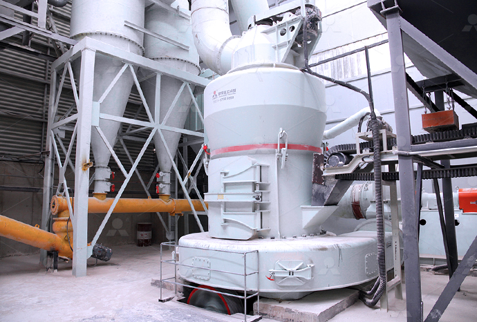
Raymond Mill
Input size:20-30mm
Capacity: 0.8-9.5t/h

Sand powder vertical mill
Input size:30-55mm
Capacity: 30-900t/h
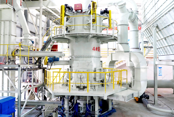
LUM series superfine vertical roller grinding mill
Input size:10-20mm
Capacity: 5-18t/h
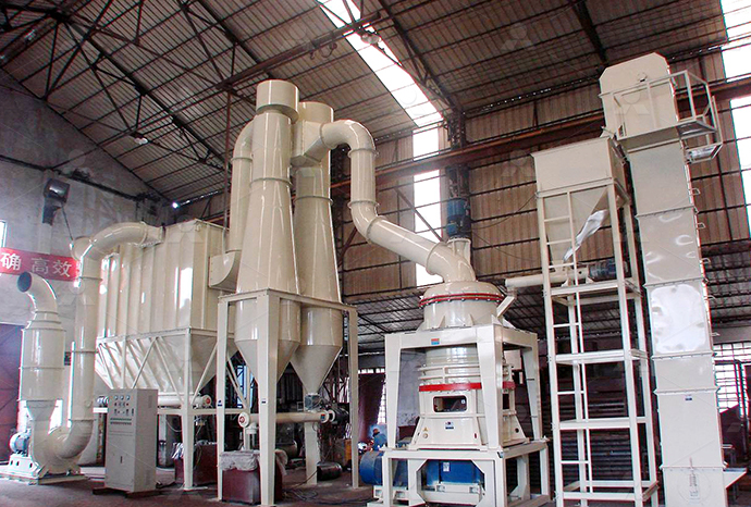
MW Micro Powder Mill
Input size:≤20mm
Capacity: 0.5-12t/h

LM Vertical Slag Mill
Input size:38-65mm
Capacity: 7-100t/h
LM Vertical Coal Mill
Input size:≤50mm
Capacity: 5-100t/h
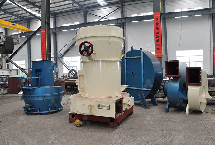
TGM Trapezium Mill
Input size:25-40mm
Capacity: 3-36t/h
MB5X Pendulum Roller Grinding Mill
Input size:25-55mm
Capacity: 4-100t/h
Straight-Through Centrifugal Mill
Input size:30-40mm
Capacity: 15-45t/h
Loss tangent angle and relative permittivity

35: Loss Tangent Physics LibreTexts
The quantity \(\tan\delta\) is referred to as the loss tangent Note that loss tangent is zero for a lossless (\(\sigma\equiv 0\)) material, and increases with increasing loss Thus, loss tangent provides an alternative way to quantify the effect of loss on the electromagnetic field within a The term tan= is called loss tangent and it represents the ratio of the imaginary part to the real part of the complex permittivity The loss tangent is also called by terms such as tangent loss, Measurement of Dielectric Material Properties Rohde SchwarzThe various dielectric properties are capacitance, permittivity, dielectric constant, loss tangent, and resistivity It is important to note that permittivity is not constant and can vary with Dielectric Theory and Its Properties EverScienceSo there is power dissipation proportional to the loss tangent (tan ) as well as relative permittivity r We sometimes use the loss factor ( rtan ) to compare dielectric materials by their power Electrical and optical properties of materials Part 2: Dielectric UCL
.jpg)
Electric Properties of Dielectrics 國立臺灣大學
–Frequencydependent permittivity and loss tangents –Environmental factors –Localized interactions (fiber weave effect) •Improper model results in inaccurate phase delay and signal The dielectric loss is reported in terms of the loss angle (δ), which has units of milliradians When δ is low valued then it is related to loss tangent (the ratio of imaginary and real parts of A comparison of measurements of the permittivity and loss angle The two type of loss are distinguishable to each other Most importantly, it is frequency dependant For microwave engineering, lossy materials are given with dielectric constants (ǫ r) Loss Tangent Singapore University of Technology and Design29 行 Dielectric loss tangent parameter (DLTP) quantifies a dielectric material's inherent dissipation of electromagnetic energy into heat, expressed by the ratio of dielectric loss factor Dielectric Loss Tangent an overview ScienceDirect Topics
.jpg)
Dielectric and ConductorLoss Characterization and
r is the real part of the relative permeability given by µ = µ0[µ0 r −jµ 00 r], ² 0 r and ² 00 r are the real and imaginary parts of the relative permittivity, ² =[²0 r −j² 00 r]²0,and²0 and µ0 are the permittivity and permeability of vacuum ²0 r provides a measure of the relative phase change as a sinusoidal signal propagates Complex wave number, index of refraction, and relative permittivity – pg 2 𝑛 å Ø Ô ß L 𝑐 𝜔 𝑘 å Ø Ô ß 𝑛 Ü à Ô Ú L 𝑐 𝜔 𝑘 Ü à Ô Ú Note in particular that 𝑛 ä and 𝑘 è will always have the same complex angle The complex relative permittivity 𝜖̃ å and complex index of refraction 𝑛Complex wave number, index of refraction, and relative permittivityof the loss tangent For very low loss materials, since tan d ≈ d, the loss tangent can be expressed in angle units, milliradians or microradians 6 r ' r '' e r e e Energy Stored per Cycle Energy Lost per Cycle Q D r r = = = = 1 tan ' e" e d Permeability that represents the energy loss term Relative permittivity Agilent Basics of Measuring the Dielectric Properties of MaterialsFor example, a material having large loss tangent due to ohmic loss might become hot when a large electric field is applied, whereas a material having large loss tangent due to delayed response might not Summarizing: The expression for loss tangent given by Equation \ref{m0132lt2} and Figure \(\PageIndex{2}\) does not distinguish between 35: Loss Tangent Engineering LibreTexts
Permittivity, Dielectric Loss and Loss Tangent YouTube
The video explains what permittivity is and how it varies with the frequency It further explains the loss angle and tangent deltais the relative permittivity of the material, and loss tangent can be expressed in angle units, milliradians or microradians 25 Resistivity Electrical resistivity (also known as specific electrical resistance or volume resistivity) is a measure of how stronglyDielectric Theory and Its Properties EverScience3231 Discussion ÑThe relation of phase angle and loss angle is shown in Fig 1 and Fig 2 Loss angle is sometimes called the phase defect angle 324 lossindex, k 9 (´r9),nÑthemagnitudeoftheimaginary part of the relative complex permittivity; it is the product of the relative permittivity and dissipation factor 3241 Discussion Ñ Standard Test Methods for AC Loss Characteristics and Permittivity the splitcylinder resonator and sample, we calculated the sample relative permittivity using (16) and the sample loss tangent using (17) In order to verify these permittivity and loss tangent measurements made with the splitcylinder resonator, we compared them to measurements made with the cylindricalcavity method [5]NONDESTRUCTIVE PERMITTIVITY AND LOSS TANGENT MEASUREMENTS
.jpg)
34: Complex Permittivity Physics LibreTexts
The LibreTexts libraries are Powered by NICE CXone Expert and are supported by the Department of Education Open Textbook Pilot Project, the UC Davis Office of the Provost, the UC Davis Library, the California State University Affordable Learning Solutions Program, and Merlot We also acknowledge previous National Science Foundation support under grant numbers 2023年6月9日 Accurate measurement of the permittivity and loss tangent of lowloss materials is essential due to their special applications in the field of ultra large scale integrated circuits and microwave devices In this study, we developed a A Novel Strategy for Detecting Permittivity and Loss 2016年6月12日 Consequently, a perfect electrical conductor (PEC) would have $ \epsilon = 0 $, since no field can form inside of its boundary It's a relative permittivity, because it is measured relatively from the permittivity of free space ($\epsilon 0$) This is similar to how dB is a relative unit, implying a ratiowhat is the physical significance of dielectric constant and loss tangent?The simulations were repeated for three different values of relative permittivity 20, 40 and 60 The relative permittivity of the reel core was 30 and the loss tangent 01 The loss tangent and loss angle as well as real permeability Permittivity and loss tangent are usually determined by means of a Schering bridge Loss Tangent an overview ScienceDirect Topics
Measurement of permittivity and loss angle for very low loss
The loss tangent of fused silica The loss angle is observed to vary approximately linearly with frequency in the RF and Microwave range For the material shown at 100 MHz,2022年5月22日 351 Microstrip Line in the QuasiTEM Approximation In this section a number of relations are developed based on the principle that the phase velocity of an EM wave in an aironly homogeneous transmission with a TEM field line is just \(c\)35: Microstrip Transmission Lines Engineering LibreTexts3231 Discussion—The relation of phase angle and loss angle is shown in Fig 1 and Fig 2 Loss angle is sometimes called the phase defect angle 324 loss index, κ" (ε r"),n—the magnitude of the imaginary part of the relative complex permittivity; it is the product of the relative permittivity and dissipation factor 3241 Standard Test Methods for AC Loss Characteristics and Permittivity Permittivity is a complex number Real component = κ‘ = εr‘= “D k” Imaginary component = εr “ Tan ( εr “/ εr ‘) = Tan δ = Loss Tangent Relative Permittivity and Loss Tangent • Relative Permittivity is the more correct way to express “Dk” above 1 GHz • Magnitude of permittivity is fairly constant at low frequenciesLowLoss Materials in High Frequency Electronics and the EPFL
.jpg)
Dielectric Constant and Loss Capacitor Phasor Diagram EEEGUIDE
so that current I may be written as K * is called the complex relative permittivity or complex dielectric constant, ε′ and K’ are called the permittivity, and relative permittivity and ε′′ and K” are called the loss factor and relative loss factor respectively The loss tangent The product of the angular frequency and ε′′ is equivalent to the dielectric conductivity σThe dielectric loss is reported in terms of the loss angle (δ), which has units of milliradians When δ is low valued then it is related to loss tangent (the ratio of imaginary and real parts of permittivity) by δ ≈ tanδ ×103 milliradians The Lynch formula [1] can be A comparison of measurements of the permittivity and loss angle 2019年3月30日 We present a systematic characterization of dielectric permittivity of 6 commonly used, lowloss polymers namely polystyrene, parylene, polyimide, SLA resin, SU8, and SUEX for the 100GHz to 2THz bands using transmission mode time domain spectroscopy The dielectric constant and loss tangent for each polymer was systematically recorded using the Dielectric Properties of LowLoss Polymers for mmW and THzWideband permittivity and loss tangent curves for the dielectric laminate of a printed circuit board are obtained For this purpose, the singlefrequency data provided by the laminate manufacturer together with propagation constant experimentally obtained from stripline measurements are used This allows for enabling the wideband simulation of interconnects while the dielectric Relative Permittivity and Loss Tangent Determination

Solutions for Measuring Permittivity and Permeability with LCR
The tangent of this angle, tan δ or loss tangent, is usually used to express the relative “lossiness” of a material The term “dielectric constant” is often called “permittivity” in technical literature In this application note, the term permittivity will be used to refer to dielectric constant and complex relative permittivityof the loss tangent For very low loss materials, since tan d ≈ d, the loss tangent can be expressed in angle units, milliradians or microradians 6 r ' r '' e r e e Energy Stored per Cycle Energy Lost per Cycle Q D r r = = = = 1 tan ' e" e d Permeability that represents the energy loss term Relative permittivity Agilent Basics of Measuring the Dielectric Properties of MaterialsFunction of Permittivity and Substrate Thickness for the 10 GHz SplitCylinder Resonator Substrate Thickness (mm) Sample Relative Permittivity 2 4 6 8 10 20 50 100 10 8 6 4 2 0 TE 012 345 011 Resonant Frequency (GHz) IPCTM650 Number 25513 Subject Relative Permittivity and Loss Tangent Using a SplitCylinder Resonator Date 01/07 Revision Relative Permittivity and Loss Tangent Using a SplitCylinderPrecise MillimeterWave Measurements of Complex Refractive Index, Complex Dielectric Permittivity and Loss Tangent of GaAs, Si, SiO/sub 2/, A1/sub 2/O/sub 3/, BeO, Macor, and Glass Abstract: Highly accurate continuous spectra of the complex refractive index and complex dielectric permittivity are given in the millimeter range for a variety of potentially useful materialsPrecise MillimeterWave Measurements of Complex IEEE Xplore
.jpg)
Real permittivity and loss tangent as a function of frequency for
Cryogenic magic angle spinning The middle layer is a dielectric made of polyimide (blue colored) with a relative permittivity of 33 and loss tangent of 4×10 3 [36]2023年10月11日 Traditional microwave design and fabrication techniques have been adopted into the terahertz domain Understanding the properties of microwave dielectric materials at terahertz frequencies is critical for accurate component design Nevertheless, terahertz properties for common microwave dielectric materials are largely unknown Hence, this paper presents Terahertz Properties of Common Microwave Dielectric Materials2015年12月29日 Relative permittivity and loss tangent The relative permittivity is a complex number and is denoted by Hence, the dielectric loss of sea ice increases with increasing incidence angle Based on their data, Vant et al developed a Microwave Dielectric Properties of Materials SpringerLink2015年5月27日 This material model assumes zero conductivity and unit relative permeability Loss Tangent involves entering a realvalued relative permittivity, \epsilonr#39, and a scalar loss tangent, \delta The relative permittivity is computed via \epsilonr=\epsilonr#39(1j \tan \delta), and the material conductivity is zeroModeling of Materials in Wave Electromagnetics Problems
Complex permittivity of some ultralow loss dielectric crystals at
For sapphire, relative permittivity uncertainty caused by neglecting expansion is therefore at least ten times smaller than the observed permittivity changes in the temperature for permittivity and the dielectric loss tangent determination Several other modes: S1 This ε is related to the dielectric permittivity of vacuum, ε 0 by a ε r, which is called the relative permittivity, delta is called the loss angle and tan delta is the loss tangentWhat the difference between dielectric permittivity 2004年2月19日 Lithium tantalate (LiTaO/sub 3/) exhibits excellent electrooptical, piezoelectric, and pyroelectric properties and a very low thermal expansion In this paper, we report measurements of loss tangent and the real part of the relative permittivity /spl epsiv//sub r/spl perp// measured in caxis LiTaO/sub 3/ crystals in the temperature range from 14 K to 295 K at Temperature dependence of permittivity and loss tangent of 2024年9月20日 Resonac’s molding compound with a low dielectric loss tangent and high relative permittivity provides excellent processability Its high relative permittivity facilitates miniaturization, and the low dielectric loss tangent allows the compound to deliver superior transmission performance even at high frequencies【Thorough Explanation】What are transmission loss, dielectric loss
.jpg)
Permittivity and Loss Tangent, Parallel Plate, 1 MHz to 15 GHz
mine the permittivity (dielectric constant or E’r) and loss tangent (dissipation factor or Tanδ) of printed wiring materials at various frequencies (from 1 MHz to 15 GHz) using a single test fixture for the measurement The permittivity and loss tangent are measured using a narrow sweep of frequency around the target or desired frequency3231 Discussion—The relation of phase angle and loss angle is shown in Fig 1 and Fig 2 Loss angle is sometimes called the phase defect angle 324 lossindex,k9(´ r 9),n—themagnitudeoftheimaginary part of the relative complex permittivity; it is the product of the relative permittivity and dissipation factor 3241 Discussion—a Standard Test Methods for AC Loss Characteristics and Permittivity dielectric substrates and spacers with high relative permittivity and loss tangent also reduce bandwidth and efficiency To overcome these issues, a proper choice of low loss and low relative permittivity dielectric layers and substrates can improve field confinement and reduce dissipationDielectrics for Terahertz Metasurfaces: Material Selection and 2021年8月22日 The effect of the dipole moment in a dielectric substrate is termed Loss Tangent Mathematically, the loss tangent is the phase angle between the resistive and reactive components of a system with permittivity A low value of loss tangents results in a "fast" substrate while large value results in a "slow" substrate The formula for Loss What is Loss Tangent? PCB Directory
.jpg)
PCB Material Properties and Their Impact on Performance of High
2023年7月5日 Understanding PCB material parameters such as relative permittivity and loss tangent allows us to discuss some important considerations for choosing the right material when designing a highspeed/high we can route traces at an angle with respect to fiber warp/fill and/or use a zigzag routing style to somewhat mitigate the Loss tangent and relative permittivity of the solder mask are contributing factors to their transmission line losses Figure 1 shows a fieldsolver simulation of the transmission line loss of a 100ohm characteristic impedance, 11inch long micro Loss Tangent and Dielectric Constant of Solder Mask Measured