


MTW European Type Trapezium Mill
Input size:30-50mm
Capacity: 3-50t/h

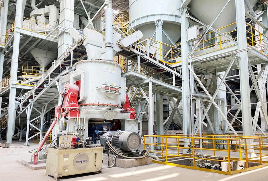
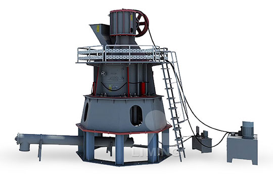
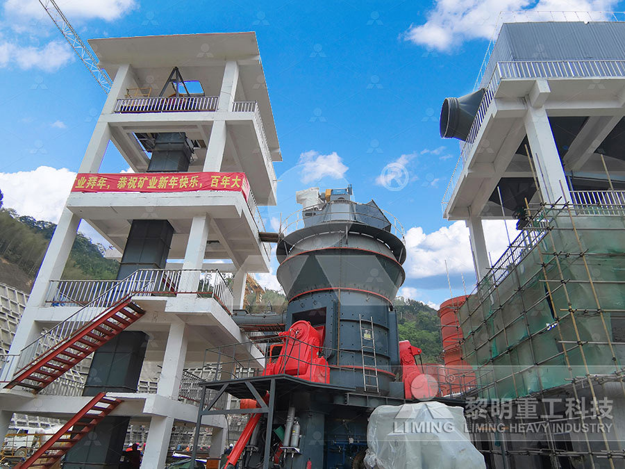
LM Vertical Roller Mill
Input size:38-65mm
Capacity: 13-70t/h
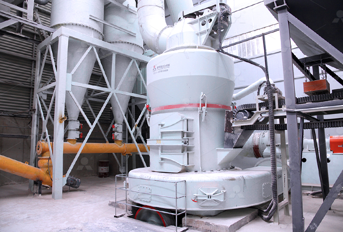
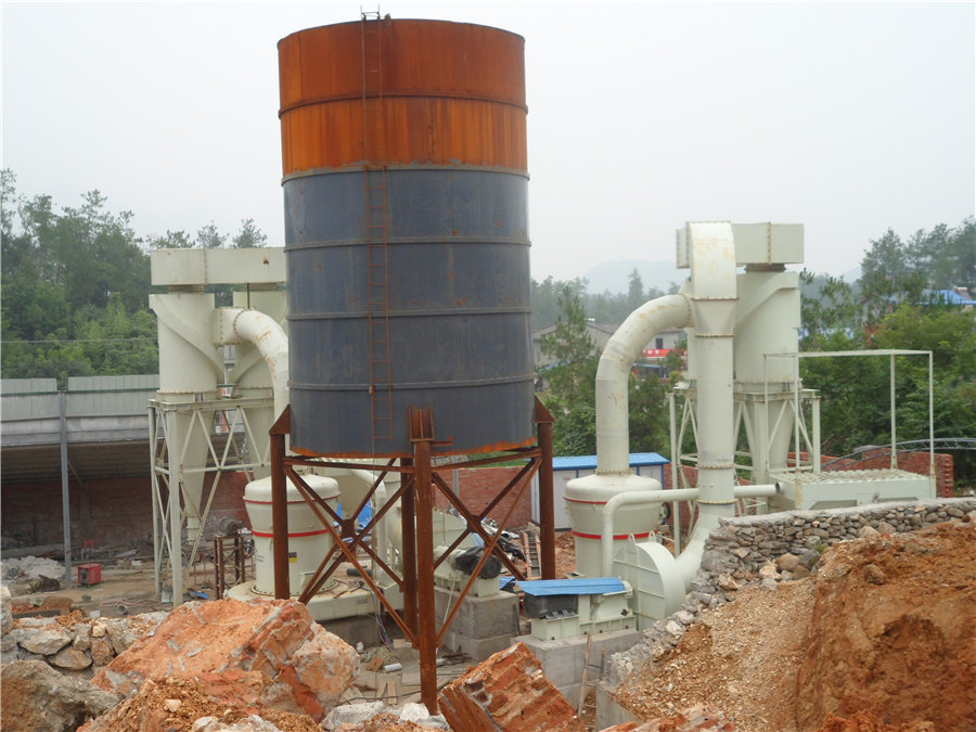
Raymond Mill
Input size:20-30mm
Capacity: 0.8-9.5t/h
Sand powder vertical mill
Input size:30-55mm
Capacity: 30-900t/h
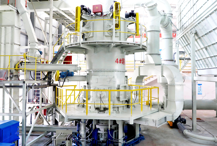
LUM series superfine vertical roller grinding mill
Input size:10-20mm
Capacity: 5-18t/h
MW Micro Powder Mill
Input size:≤20mm
Capacity: 0.5-12t/h

LM Vertical Slag Mill
Input size:38-65mm
Capacity: 7-100t/h
LM Vertical Coal Mill
Input size:≤50mm
Capacity: 5-100t/h
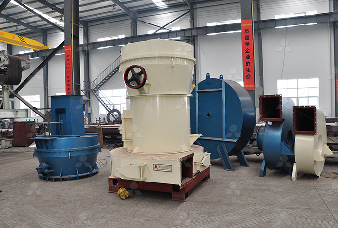
TGM Trapezium Mill
Input size:25-40mm
Capacity: 3-36t/h
MB5X Pendulum Roller Grinding Mill
Input size:25-55mm
Capacity: 4-100t/h
Straight-Through Centrifugal Mill
Input size:30-40mm
Capacity: 15-45t/h
PLC ladder diagram
PLC Ladder Logic Programming Tutorial (Basics)
2017年9月4日 Ladder logic (also known as ladder diagram or LD) is a programming language used to program a PLC (Programmable Logic Controller) It is a graphical PLC programming Building Logic with Ladder Logic Now, after you have learned about these new set Ladder Logic TutorialCreate, edit and run ladder logic diagrams with an interactive tool Learn from documentation, tutorials and sample diagrams, or share your own creations with othersOnline PLC Ladder Logic Simulator: Learn practice 2024年2月27日 Learn how to program a PLC using ladder logic diagrams, a graphical representation of relay logic See the structure, components, advantages, disadvantages, applications and examples of ladder logicPLC Programming Ladder Logic GeeksforGeeks
.jpg)
PLC Programming How to Read Ladder Logic
Learn the basics of ladder logic, a popular PLC programming language that mimics electrical circuits See examples of ladder diagrams, circuit branches, and how to troubleshoot common problems2018年12月10日 梯形图是一种PLC编程语言,也被称为梯形逻辑(Ladder Logic)。 之所以称为梯形图,是因为 这种程序由一条条水平线构成,看起来很像梯子。 梯形图是为电气工程师发明的,它是一种图形化的编程语言,这意味 PLC编程入门【梯形图】 学习软件编程2021年6月6日 梯形图(Ladder Diagram)是一种图示语言,用于表示可编程逻辑控制器(PLC)的逻辑控制程序。 它是最常用和广泛接受的 PLC 编程语言之一。 梯形图 的名称源自其图示形状,整个 程序 看起来像一张梯形。五看懂plc梯形图程序 CSDN博客2020年4月29日 PLC Programming: Ladder Logic Diagram (Photo from PLCacademy) The ladder logic diagram consists of two fundamental parts, which you can see as the vertical and Basic PLC Programming – How to Program a PLC using Ladder

Ladder Logic Basics
2021年2月16日 Learn how to program a PLC using ladder logic, a graphical language that resembles relay circuits Find out the seven basic parts of a ladder diagram, the binary and logic concepts, and the fundamental logic functions2019年11月3日 Ladder diagram, better known as ladder logic, is a programming language used to program PLCs (programmable logic controllers) This article will briefly describe what ladder logic is and go over some examples of how it Ladder Logic in Programmable Logic Controllers (PLCs)2015年2月9日 Similarities with Ladder Diagrams Ladder logic was designed to have the same look and feel as electrical ladder diagrams, but with ladder logic, the physical contacts and coils are replaced with memory bits Let’s take a Ladder Logic Tutorial with Ladder Logic Symbols2022年11月3日 Pada Ladder diagram, bahasa pemrograman yang digunakan untuk membuat program untuk mengontrol sistem PLC disebut dengan ‘Ladder Diagram Language’ atau ‘Ladder Logic Language‘ Ini telah ditandai dengan Pengertian Ladder Diagram Pada PLC
What is Ladder Diagram Programming ? Basics of
None of the contacts or coils seen in a Ladder Diagram PLC program are real; rather, they act on bits in the PLC’s memory, the logical interrelationships between those bits expressed in the form of a diagram resembling a circuit 2015年6月28日 Ladder logic symbols are a set of symbols used in PLC ladder diagrams Download all the IEC 611313 ladder diagram symbols as DWG, PDF and PNG files hereLadder Logic Symbols All PLC Diagram Symbols PLC Academy2021年3月15日 Ladder Diagram is one of the most popular PLC programming languages, actually if you can learn and master Ladder Diagram programming, it becomes much easier to learn other PLC programming languages like Structured Text (ST) Contents 1 Symbols used in a Ladder Diagram;The Basics of Ladder Diagrams for Programming PLCs2020年4月29日 Ladder Logic Diagram The most commonly used PLC programming language is the Ladder Logic Diagram The reason for its popularity is that Relay Logic Diagrams were closely resembled by the Ladder Logic Diagrams When the PLC was invented, designers found a way to use the existing knowledge of the Relay Control System designers for programming Basic PLC Programming – How to Program a PLC using Ladder
.jpg)
Ladder logic Wikipedia
Part of a ladder diagram, including contacts and coils, compares, timers and monostable multivibrators Ladder logic is widely used to program PLCs, where sequential control of a process or manufacturing operation is requiredLadder logic is useful for simple but critical control systems or for reworking old hardwired relay circuits As programmable logic controllers became more 2015年11月30日 PLC Ladder Programming A very commonly used method of programming PLCs is based on the use of ladder diagrams Writing a program is then equivalent to drawing a switching circuit The ladder diagram consists of two vertical lines representing the power railsPLC Ladder Diagrams for Electrical EngineersThe PLC reads a Ladder Diagram from left to right, top to bottom, in the same general order as a human being reads sentences and paragraphs written in English However, according to the IEC 611313 standard, a PLC program must evaluate (read) all inputs (contacts) Ladder Diagram (LD) Programming Contacts and CoilsAre you new to PLC programming? Are you looking for a tutorial of the basics of PLCs? Look no further! In this episode, we cover Ladder Logic Ladder Logic (PLC Basics: Ladder Logic YouTube
A Beginner's Guide to PLC Programming using Ladder
2023年1月30日 Learn PLC programming with examples The IEC 61131’s five programming languages specified in the IEC 611313 Standard are Ladder Diagram, Instruction List, Function Block Diagram, Structured Text, and 2019年2月20日 Remember, the PLC executes ladder logic one instruction at a time – from top to bottom If you put the set and reset in different POU’s then the result will come from the last POU the PLC calls and executes They can be Ladder Logic Tutorial Part 2: Building Logic PLC The simple PLC ladder diagram (LD) commands consist of contacts and coils, arranged in sequences that mimic industrial electrical control structures However, a quick look at any PLC program will show advanced commands including Ladder Diagram (LD) Structure CommandsIn an effort to make PLCs easy to program, their programming language was designed to resemble ladder logic diagrams Thus, an industrial electrician or electrical engineer accustomed to reading ladder logic schematics would feel comfortable programming a PLC to perform the same control functionsProgrammable Logic Controllers (PLC) Ladder Logic
.jpg)
Programación LADDER (PLC) MacroPLC
MacroPLC Trainer Sistema de Programación Ladder El nombre de este método de programación (que significa escalera en inglés) proviene de su semejanza con el diagrama del mismo nombre que se utiliza para la documentación de circuitos eléctricos de máquinasLadder Logic Programming Examples and PLC practical problems on Timers, Counters, Motor Control PLC Programs with RealTime world examples To develop the ladder diagram and mimic the diagram for the bottle filling process In this process, the Ladder Logic Programming Examples PLC Practical ProblemsLadder Logic (LAD) for S7 300 and S7400 Programming Reference Manual, 04/2017, A5EAA 3 Preface Purpose This manual is your guide to creating user programs in the Statement List programming language Ladder Logic The manual also includes a reference section that describes the syntax and functions of the language elements of Ladder LogicLadder Logic (LAD) for S7300 and S7400 Programming2022年4月23日 Simbol Ladder Diagram PLC – Simbol simbol ladder diagram yang di gunakan dalam pemrograman ladder diagram sebenarnya mirip dengan sirkuit kontrol logika relai tradisional Jika Sahabat memiliki pengetahuan dasar tentang rangkaian listrik maka memulai pemrograman dengan bahasa pemrograman Ladder diagram sangatlah mudahSimbol Ladder Diagram PLC
.jpg)
PLC Programming Basics using Ladder Logic Learn Robotics
2024年4月25日 Now that we have a general overview of how the PLC executes the program scan cycle, we can talk about ladder logic fundamentals Ladder Logic Fundamentals (How to read and write Ladder Diagrams) Programs in Ladder Logic are written differently than embedded or flowchart programmingEdit the imported Ladder Diagram model from within Simulink by using the plcladderlib library After importing the ladder diagram code into Simulink, simulate it Generate C code from the imported ladder diagram and integrate the code into your existing C Ladder Diagram Integration MathWorks2020年6月4日 PLC Ladder Logic Programming examples The PLC ladder logic programming examples that I am about to share with you guys will really help you in developing complex ladder logic diagrams The PLC ladder logic PLC Ladder Logic Programming Examples with A ladder diagram is read from left to right and from top to bottom, Figure 13 showing the scanning motion employed by the PLC The top rung is read from left to right Then the second rung down is read from left to right and so onIntroduction to PLC Ladder Diagrams Free PLC
.jpg)
PLC 梯形图编程基础 知乎
梯形图(LAD)是PLC编程的最佳可视化语言,看起来非常的类似于继电器电路图 1什么是梯形图 梯形图是一种PLC编程语言,也被称为梯形逻辑(Ladder Logic),之所以称为梯形图是因为这种程序语言是由一条条水平线构成的, Logika Dasar PLC Programming Keunggulan Ladder diagram dibanding dengan bahasa pemrogramman yang lain terletak pada kemudahan dalam memasukkan logika Prinsip logika True/Flase, Nyala/Mati terbentuk dari kombinasi rangkaian Apa itu Ladder Diagram dalam PLC Programming?2022年8月5日 Ladder logic programming is the language that helps in constructing software and programs for PLC controllers It presents the program in the form of ladder diagrams that are based on circuit illustrations This article gives a comprehensive view of ladder logic programming and its benefits in the industrial space What is ladder logic programming?Ladder logic programming: A detailed insight Schneider Electric 2023年11月16日 Ladder logic symbols, or bit logic instructions, are the basis of ladder diagram programming, a graphical language widely used in industrial control systems Ladder logic symbols are comparable to the vocabulary of this language, representing various logical operations, inputs, outputs, and other control system componentsLadder Logic Symbols: A Comprehensive Guide Wevolver
.jpg)
五看懂plc梯形图程序 CSDN博客
2021年6月6日 梯形图(Ladder Diagram)是一种图示语言,用于表示可编程逻辑控制器(PLC)的逻辑控制程序。它是最常用和广泛接受的PLC编程语言之一。梯形图的名称源自其图示形状,整个程序看起来像一张梯形。它由水平的横越线组成,这些横越线被垂直的侧栏划分为多个 2018年12月10日 当plc扫描周期开始,plc将首先检查所有输入的状态,然后将输入状态(0或1)写入内存中, 如果输入是low,那么对应的内存位置位0,如果输入是high,则对应的内存位置为1 输出线圈指令 每个指令本身在plc内存中也有个位置,plc会将指令的结果存入。PLC编程入门【梯形图】 学习软件编程2015年9月13日 In this lesson we'll take an introductory look at ladder logic diagrams, the principle means electrically controlled systems use to document and convey not oBasic Ladder Logic (Full Lecture) YouTubeSimulador de PLC y Ladder en línea gratuito La simulación de PLC es una forma de desarrollar y probar algoritmos El software de simulación de PLC está diseñado para desarrollar lógica de control y analizar el sistema con un modelo sistemático El aprendizaje de un simulador de PLC facilita la depuración de los PLCSimulador online de PLC en Ladder MasterPLC
43.jpg)
10 RealWorld Plc Ladder Diagrams You Can Learn
A PLC ladder diagram is a graphical programming language used to program programmable logic controllers (PLCs) It is based on ladder logic, which represents the logic of a control circuit in a manner similar to the relay logic Ladder Diagram atau Ladder Logic adalah bahasa dan logika pemrograman yang paling banyak digunakan dalam PLC (Programmable Logic Controller) Dalam dunia sistem otomasi, bahasa pemrograman ini menjadi salah satu yang wajib Pengertian Ladder Diagram serta Kelebihan dan Introduction Siemens offers one of the most intuitive and userfriendly development environments This makes it a great starting point for those who want to start practicing PLC programming In this tutorial, we will explore the An Introduction to Basic Ladder Logic Instructions inA PLC ladder diagram is a visual programming language used in programmable logic controllers (PLCs) to create and implement control programs for industrial applications It is a graphical representation of the control logic that the PLC uses to make decisions and control the operation of a machine or processA comprehensive guide to PLC ladder diagram tutorials
.jpg)
Ladder Logic Symbols PLC Programming in RSLogix 5000
Ladder Logic symbols are foundational elements that are memorized by every plc programmer They’re essential to know if you plan to do any work with this PLC programming language In this tutorial, we will discuss each symbol, the functionality it brings to the ladder logic plc programming language as well as illustrate two examples where they may be used2020年7月22日 Therefore, a rung is the contact symbology required to control an output in the PLC A complete PLC ladder diagram program then consists of several rungs, each controlling an output interface which is connected to an output field Ladder Diagrams Automation Community2023年7月17日 Just as the name suggests, Ladder Logic is a type of programming that resembles a ladder It's a graphical language, meaning it's based on images or symbols, rather than text, which makes it more accessible for people who don't have a background in coding Ladder Diagram (LD) The Ladder Diagram (LD) is the language used for creating ladder logicUnderstanding Ladder Logic in IEC 611313 Learn Ladder LogicEdit the imported Ladder Diagram model from within Simulink by using the plcladderlib library After importing the ladder diagram code into Simulink, simulate it Generate C code from the imported ladder diagram and integrate the code into your existing C Ladder Diagram Integration MathWorks
.jpg)
Programmazione PLC / Come leggere la logica ladder
Scala di Logica di Programmazione PLC Ramo del Circuito Avanzato Esempio Avanzate Circuito di Ramificazione Logica Ladder Pratica Ora che hai familiarità con il modo in circuito rami lavorare in logica ladder, è importante per la pratica di analisi logica, come si farebbe in campo, La maggior parte del tuo lavoro come programmatore PLC guarderà i gradini della logica e 2018年5月25日 The ladder logic programming is commonly used to program PLCs A PLC takes input from field devices and based on the programming instructions controls output devices Writing a program is then equivalent to drawing a switching circuit The ladder diagram consists of two vertical lines representing the power rails Circuits are connected as horizontal lines, ie, How to write a PLC ladder logic program? AutomationForum